ELECTRIC FLIGHT PRIMER


Written by David Menzies during his time at WRCS.

The following are notes, comments and formula that I have found useful in understanding and designing electric flight systems for model aircraft.

First the disclaimer, this is simple first princlple stuff – a broad brush if you like suited to normal non specialist type models. There are many other more sophisticated programs and information on the web if you require more detailed info.


GENERAL NOTES

Watts

From Ohms law - Watts are Volts × Amps.


Lipo cell voltage

max       4.20v

store      3.80v

nominal    3.70v

minimum   3.20v


Battery “C” rating

Every battery has a C rating, this is the theoretical maximum current discharge so a 1000ma 25c battery can deliver 25amps.

Within reason the higher the C rating the better, higher C rated cells have a lower internal resistance and more punch in their power delivery.

Always use a balance charger and for safety charge at a rate of 1c (a 1000ma cell would be charged at 1amp or 1000ma).


ESC

The “esc” is the heart of an electric model and if it fails so does the model.

SBEC's are a better choice with digital servos.

A programming card is worth having to set up the esc with brake and timing functions etc.


Reliabilty

For a reliable system the 80% rule is a good start point.

take 1760ma from a 2200ma battery.

use 24c from a 30c battery.

draw 24amps from a 30amp esc.

Care for your batteries, check before and after use, store charge for periods over 2 or 3 days.


Equipment

Use a safety/arming switch on your transmitter.

Invest in a Wattmeter and use it, it is the only way to know is going on with your power system.


Flying Technique

Manage the throttle, power can be saved and flight endurance increased.


Further info

http://www.cornwallaeromodellers.ca/PDF_Files/EPS.pdf


POWER SYSTEM CALCULATION


Step 1

Weigh everything - airframe, radio, motor and battery (make an assumption) in lbs, it can be tweaked in a recalc later if required.

The total power can now be worked out as follows – 100watts per 1 lb weight (this is a good all round number that will fly most sport models)

So a 3lb model needs 300watts.

The above can be modified as follows if desired.

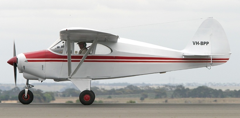
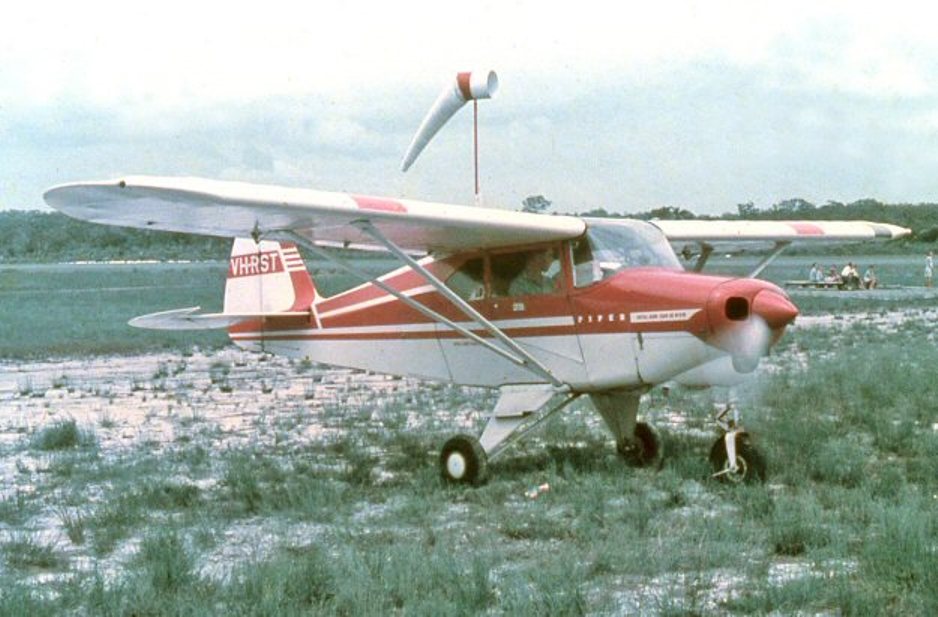
70 to 80 watts/lb – Piper Cub style, light vintage model, glider, modest performers.

100 watts/lb – general sports model.

120 to 130 watts/lb – brisk sports perfomance.

150 watts/lb – sports performance with good vertical

175 watts/lb – minimum for 3D

200 watts/lb – minimum for EDF


Battery voltage (lipo cell count)

Modern esc's will generally handle up to 6s so it is better to up the volts rather than the amps in the search for the watts calculated above.


Physical motor size

Sift through the motor specs, they always give either watts or volt and amps (watts is volts*amps) and find some suitable candidates. The laws of physics always apply so no matter who makes the motor you can't get a quart out of a pint pot – the motor has to be a certain size to dissipate the power.


kv of motor

kv is the theoretical speed the motor (unloaded) will achieve so a 1000kv motor with a 3s (11.1v) pack will run at 11,100rpm, whereas on 4s (14.8v) it would be 14,800rpm

Consider the model type, a glider/vintage (slow) model performs best with a large slow revving prop whereas a pylon racer needs a small fast revving prop

A glider on 3s running at say 8,500rpm would need a 766kv motor (8500/11.1) whereas a sport aircraft at say 11,000rpm would need a 990kv motor(11000/11.1). It is unlikely you will get a motor that matches your calculations exactly but it gives a zone to look in based in the type of performance you require.


Battery Capacity

The battery capacity is “the size of the fuel tank”.

Pick a battery that suits the purpose, a glider only needs 2 or 3 good climbs (each run about  30 secs) for 10 mins flying in average conditions. For example my 2m Spirit draws about 20amps on 3s (220watts) so using a 1000ma 20c battery would give me my 20 amps (1*20c). A 1000ma cell can in theory deliver 1 amp for 60 mins or 20amps for 3 mins(60mins/20amps) 3 climbs equates to about 1.5 mins,well within the possible 3 mins.

For power models I work the numbers on a 5 minute motor run which in practice equates to some 7 or so minutes flying because the prop unloads in the air and the power use drops.


Stan has finished the Tri Pacer. Click HERE to download his report on finalising the build and getting it into the air.


Oily Hand August 2016

Monday was raining, Tuesday the same and Wednesday was worse than both put together! Thursday wasn’t raining and so I packed the car and set off for Cowra, the forecast wasn’t good but this was the Oily Hand weekend and not to be missed. Four and a half hours later the weather had improved (despite the forecast) and I checked into the Cowra Hotel – no stars on this one but all I needed was a bed and access to a shower and toilet and you can’t complain at $30 per night!

The next morning there was a thick layer of ice on the windscreen (thank goodness for the Amex card – don’t leave home without it) and once cleaned off it was time to head for the field and check in. The sky was blue, there was no wind worth talking about – things were looking up. The usual paddock had been planted with canola so there was only a control line (C/L) space available, free flight and small radio was to take place on the next huge paddock planted with Lucerne but we could walk over it.


OH is aimed at diesel and small R/C with some low key competitions. There is always a “Model of the Meet” and for this, the 10th year it was the Apex designed in 1958. This is mine complete with a 1962 ED Cadet which has almost enough power to strip a rice pudding of its skin …….. but not quite. It flies well, I test flew it at our field with the help of Dave Pound and managed 2 circuits before meeting a tree! Yes, that’s Stan Begg alongside me with his Javelin, a model designed in  with a rapid climb rate pow ered by a Taipan 2.5 and a very impressive glide (one flight he timed at 14 minutes from a 20sec engine run).

Saturday morning was just as cold but soon warmed up to T shirt temp after flying started at 7.00am with egg and bacon cooked at the field!  We had the Concours event for the Apex where 21 had been entered – mine came 3rd, I was well pleased.

This was followed by the PAA Load comp for the Apex where you load a bag of sand in it and still try to complete a 30 second flight. Mine managed about 100 grams, the winner carried 750 grams – about twice the weight of the plane – amazing!

This event was followed by a “SAMs Scramble”. Make as many flights as you can in 30 minutes (maximum duration 2 minutes) while taking off from your allocated place and retrieving it from the official landing area and returning to your starting point before re-starting and launching again. I flew my Tomboy with Mills .75 power while Stan acted as my time keeper. We got a total of 14 minutes, far below the winner with over 15.

In between the events there was heaps of general flying with people like Warren Brown and his collection of interesting craft. This is his profile DH twin (Yes! Twin .5cc diesel powered) that flew remarkably well.

I met Don Howie there who is well known in SAM circles as well as a friend of our old mate Peter Leaney now in Adelaide.

Stan and I did a lot of Tomboy flying, it is really a delightful design from the famous designer Vic Smeed. Here we are, mine is only 6 years old, Stans has a 65 year old Mills .75 in it and is at least 10 but he thinks it may be time to build another.

Sunday started at 8.00am again – it was cold – with a Catapult Glider Scramble. It goes TWANG, time it, retrieve and keep doing that for 30 minutes. Here are the intrepid entrants with their conventional planes except Sam (next to me in the striped shirt) who had a canard that was superbly trimmed. It spiralled vertically up from the launch before setting off on a typically 1 minute or more flight. My best was 14 seconds which explains why I came last.


This was followed by the inevitable Plank Racing which involves fly a set of C/L manoeuvres in the fastest time. I managed a DNF again (I really should practise more than once per year!)  including some periods where I didn’t even know where the plane was! But it’s all good fun!

Lunchtime saw the presentation of various prizes and then the gradual movement of people towards home. Another great weekend over and a particularly good Oily Hand Day, if you have a small diesel build something and try it. 

Mike Minty


You can download the PDF for reading by clicking HERE

It is a largish file so give it a minute or so before panicking!

Building a 1/3rd Scale Piper Tri Pacer

At last all the inside stuff is now completed and I can finish covering the fuselage. I'm going to use natural colour Solartexand will cover the sides first followed by the top. I'll leave the bottom covering off until I have finally balanced the plane in case i've got to move batteries or add tail weight.

The fabric covering on the sides extends forward to a line just forward of the cabin where there is a transition to aluminium sheet which I hope to duplicate with fibreglass.


All done Solartex is lovely stuff to use and can make us all look good.

I'm going to glass the nose with 3/4 oz cloth which I'll hit with a coat of grey primer that I can sand down with wet and dry to give me the smooth finish that will look like the aluminium skin of the full size.


My technique with using 3/4 oz glass cloth has evolved over the years and one of the things I find absolutely essential is to have a set of sharp scissors and I mean sharp. The cloth is so thin and unstable in the weave that you can't afford to pull it in any direction when cutting to shape.

Once I've placed my over size piece on the plane I tack it down the middle, stretch it out to the corners and tack it there. I then use a small, cheap disposable roller to roll on the resin then, using a dry roller run it over the area to absorb any excess, works for me and gives a nice consistent finish. The rollers cost about $3 ea and can be cleaned with metho but the metho used to clean them costs nearly as much as the roller.


The plans suggest scale opening doors but I was concerned that they would have weakened the structure too much so with the exception of the luggage door I settled for simulating the cabin doors by packing off thin G10 fiberglass sheet with 0.3mm ply strips.

Next was the window glazing. The side windows were a piece of cake to make as they are all flat, the windscreen is another matter. The plans have a template of the screen but I must say I only thought it would be good enough to be a starting point so I photocopied the template onto ordinary 80 gsm paper and cut it to 6mm oversize. I fitted the paper template to the aircraft and was pleasantly surprised to see a near perfect fit, a bit of trimming around the wing root and removing the oversize resulted in an accurate template that I could transfer to PET sheet.


A bit of accurate scissor work and you beauty, a really good fit. I didnt believeit was going to be as easy as it was. Thanks for the template Wendell, it sure saved a lot of stuffing around. I can now fit the forward braces and lay a coat of primer on all the glassed bits. After I paint the anti glare panel I will be able to glue the windscreen in place.


Masked up for priming on the nose, U/C legs, doors and hatch


The windscreen is now on and I've included a 1/3rd scale map on the dash of Garrigal Park in case Happy the pilot gets lost. The cabin is now sealed and the dreaded paint job is getting close. The base coat is Daytonna White and then after some pretty extensive masking  a decorative coat of Cadilac Red.

I've managed to find one last bit of the build that gives me the opportunity to delay the dreaded painting. The wing struts on the Tri Pacer are operational and have to be properly engineered to take the strain of a 15kg plus aeroplane pulling G forces.

I'm going to make them out of several lengths of 3/8" x 1/4" spruce that will be laminated around and over the end fittings. I have always envisaged that the struts would be permenantly fixed at the wing end and then bolted to tangs fixed to the undercarriage plate at the fuselage end. To do this I required swivel joints at the wing / strut junction. Google came to the rescue and after a search found 3mm rod ends at the extraordinarily named site "Bangood"


A 3mm diameter threaded rod is epoxied into trenches on the wing ends of the struts for the rod ends. The rod ends will give me about + or - 3mm of adjustment. The fuselage end consists of a shaped plate sandwiched between two aluminium sheet pieces to form a flat fork that will go over the fuselage tang and be bolted through.

The front strut is made up from 4 x 3/8" x 1/4" pieces of spruce and the rear strut 2 x 3/8" x 1/4" spruce. All gluing was with Hysol.

Belt and braces meant that I had to drill and tap and fit three 1/2" 4-40 countersunk screws through the strut and aluminium plates at the fuse end.

I've put heatshrink tubing over all the ends to give me the look of cuffs, I hope, after all is painted

Well, that's it, painting to go, wish me luck

Cheers

Stan